
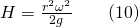
Vortices can occur naturally or be produced in a laboratory. There are two types of vortices: free vortices and forced vortices. A free vortex is formed, for example, when water flows out of a vessel through a central hole in the base. No external force is required to rotate the fluid, and the degree of rotation is dependent upon the initial disturbance. Whirlpools in rivers and tornadoes are examples of natural free vortices. A forced vortex, on the other hand, is caused by external forces on the fluid. It can be created by rotating a vessel containing fluid or by paddling in fluid. Rotational flow created by impellers of a pump is an example of a forced vortex in turbomachinery.
Studying natural phenomena such as hurricanes, tornadoes, and whirlpools (free vortices) requires a full understanding of vortex behavior. It is also critical for engineers and designers to be able to characterize forced vortices generated in machinery, such as centrifugal pumps or turbines. Vortices often have adverse effects, as have been seen during hurricanes, tornadoes, or scour holes created downstream of a dam outlet; however, understanding vortex behavior has enabled engineers to design turbomachinery and hydraulic structures that take advantage of these phenomena. For example, hydrodynamic separators have been developed, based on vortex behavior (swirling flow), to separate solid materials from liquids. This type of separator is used in water treatment plants.
The objective of this lab experiment is to study and compare the water surface profiles of free and forced vortices.
This experiment is performed by measuring the water surface profiles of a number of free and forced vortices, and observing the differences. We will study the profiles of free vortices that are produced when water flows from orifices of different diameters that are installed at the base of a tank. Varying the size of the orifice creates changes in the flow rate, thereby changing the rotational speed and size of the vortex profile. Forced vortices are created due to external forces, so we will increase the rotational speed throughout the experiment to study the theoretical and experimental relationships between the vortex surface profile and angular velocity.
The free and forced vortices apparatus consists of a transparent cylindrical vessel, 250 mm in diameter and 180 mm deep, with two pairs of diametrically opposed inlet tubes of 9.0 mm and 12.5 mm diameter. The 12.5 diameter inlet tubes are angled at 15° to the diameter in order to create a swirling motion of the water entering the vessel during the free vortex experiment (Figure 8.1a). An outlet is centrally positioned in the base of the vessel, and a set of push-in orifices of 8, 16, and 24 mm diameter (Figure 8.1b) is supplied to reduce the outlet diameter to a suitable value and produce free vortices of different sizes. The vortex surface profile is determined by a measuring caliper (Figure 8.1c) housed on a mounted bridge, that measures the diameter of the vortex at various elevations. This provides the coordinate points that are required for plotting the free vortex profile [8].
The forced vortex is created by positioning a bushed plug in the central hole of the vessel and introducing the flow through 9 mm inlet tubes that are angled at 60° to the diameter. The water inflow from these tubes impinges on a two-blade paddle. The water exits the vessel via the 12.5 mm angled inlet tubes that are used as entry tubes for the free vortex experiment. The two-bladed paddle rotates on a vertical shaft supported by the bushed plug. A bridge piece mounted on top of the vessel houses a series of needles (Figure 8.1d) to determine the coordinates of the forced vortex profile [8].
A 3-way valve allows water to be diverted through the 12.5 mm inlet tubes for the free vortex experiment, and 9 mm inlet tubes for the forced vortex experiment.
 of different sizes: 8mm, 16mm, and 24mm. The third image shows the free vortex measuring caliper. And the fourth image shows 6 different force vortex measuring probes." width="1024" height="576" />
Figure 8.1: a) P6238 CUSSONS free and forced vortex apparatus, b) push-in orifices, c) free vortex measuring caliper, d) force vortex measuring probes
Two types of vortices are distinguished in the dynamics of the motion: forced and free vortices. The forced vortex is caused by external forces on the fluid, such as the impeller of a pump, and the free vortex naturally occurs in the flow and can be observed in a drain or in the atmosphere of a tornado.
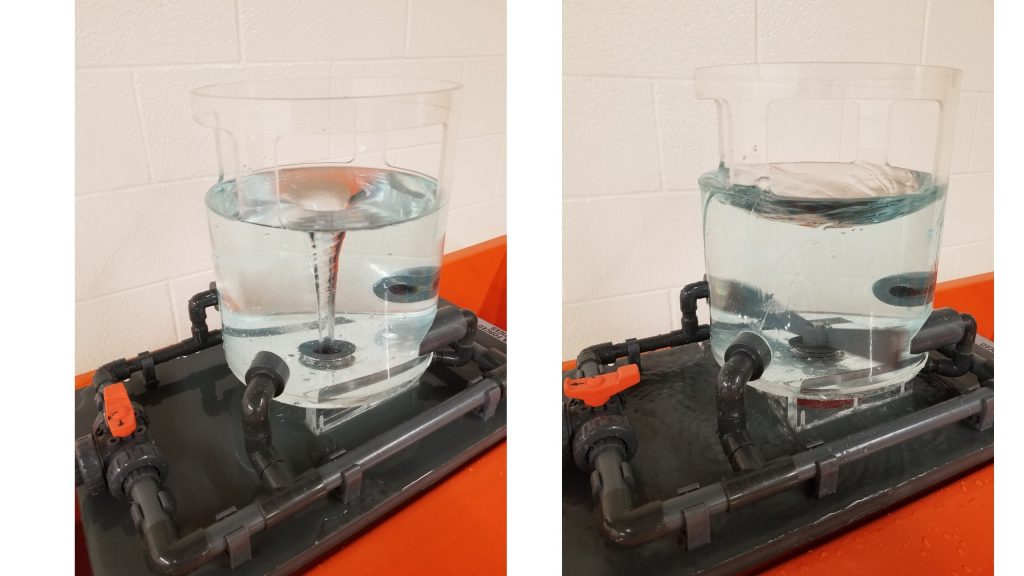
A free vortex is formed when water flows out of a vessel through a central hole in the base (Figure 8.2). The degree of the rotation depends on the initial disturbance. In a free cylindrical vortex, the velocity varies inversely with the distance from the axis of rotation (Figure 8.3).
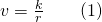
The equation governing the surface profile is derived from the Bernoulli’s theorem:
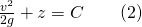
Substituting Equation (1) into (2) will give a new expression:
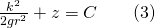
 (Figure 8.4)
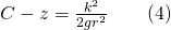
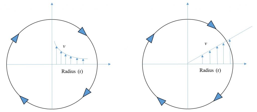
This curve is asymptotic to the axis of rotation and to the horizontal plane through z=c.
When water is forced to rotate at a constant speed ( ) (Figure 8.2), the velocity will be also constant and equal to:
The velocity head (or kinetic energy) can be calculated as:
Substituting Equation (5) into (6) results in:
If the horizontal plane passing through the lowest point of the vortex is selected as datum, the total energy is equal to:
where ho is the pressure head at the datum. Substituting hc from Equation (7) into (8) gives:
This is the equation of the water surface profile, which is a parabola (Figure 8.4).
 line measuring the radius. The velocity profile of a forced vortex on the right shows the vortex (v) with a radius increasing in a linearally." width="512" height="224" />
A YouTube element has been excluded from this version of the text. You can view it online here: uta.pressbooks.pub/appliedfluidmechanics/?p=239
This experiment will be performed in two parts: free vortex and forced vortex.
Note: The vortex profile tends to wander, so the vortex diameter- measuring gauge arm should be positioned at 90° to the main arm. This allows a meaningful vortex diameter measurement to be made.
Note: If the water level fluctuates, raise the free end of the outlet tube above the grade line of the water in the vessel, and then lower it again into the bench tank. Doing this will ensure that water discharges at the same rate that it flows in, thereby helping to maintain the water level.
Please visit this link for accessing excel workbook for this experiment.
Use the following tables to record your measurements.
| D (mm) | 24-mm Orifice | 16-mm Orifice | 8-mm Orifice |
| H (mm) | |||
| 80 | |||
| 70 | |||
| 60 | |||
| 50 | |||
| 45 | |||
| 40 | |||
| 35 | |||
| 30 | |||
| No. of Revolutions (N) | T (sec) | Distance from center, r(mm) | ||||||
| 125 (edge) | 110 | 90 | 70 | 50 | 30 | 0 | ||
| Measured height, H(mm) | ||||||||
| 10 | ||||||||
| 20 | ||||||||
| 40 | ||||||||
| 50 | ||||||||
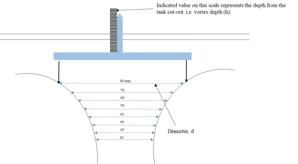
Record the coordinate points (D and H) for the three vortex profiles, using Figure 8.5 and the Raw Data Table – Free Vortex.
| 24-mm orifice | 16-mm orifice | 8-mm orifice | |||
| D (mm) | H (mm) | D (mm) | H (mm) | D (mm) | H (mm) |
| 80 | 80 | 80 | |||
| 70 | 70 | 70 | |||
| 60 | 60 | 60 | |||
| 50 | 50 | 50 | |||
| 45 | 45 | 45 | |||
| 40 | 40 | 40 | |||
| 35 | 35 | 35 | |||
| 30 | 30 | 30 | |||
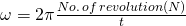
For all series of experiments with N=10, 20, 40, and 50,
| Distance from the center, r (mm) | N=10 | N = 20 | N = 40 | N = 50 | ||||||||
| ω (rad/s) | H (mm) cal. | H (mm) meas. | ω (rad/s) | H (mm) cal. | H (mm) meas. | ω (rad/s) | H (mm) cal. | H (mm) meas. | ω (rad/s) | H (mm) cal. | H (mm) meas. | |
| 0 | ||||||||||||
| 30 | ||||||||||||
| 50 | ||||||||||||
| 70 | ||||||||||||
| 90 | ||||||||||||
| 110 | ||||||||||||
| 125 | ||||||||||||
cal.= calculated; meas.= measured.
Use the template provided to prepare your lab report for this experiment. Your report should include the following:
This page titled 1.8: Experiment #8: Free and Forced Vortices is shared under a CC BY 4.0 license and was authored, remixed, and/or curated by Habib Ahmari and Shah Md Imran Kabir (Mavs Open Press) via source content that was edited to the style and standards of the LibreTexts platform.